Seasoned SMI Testing Experts Offer Savings and Efficiencies Above and Beyond Traditional Audits
Steam Management, Inc. (SMI) has collectively surveyed, designed, and upgraded steam systems in hundreds of facilities. The years of direct experience has educated our team on common problem areas and where to find savings opportunities.
Routinely, while onsite to execute steam trap upgrade survey, testing, design, and installation projects, we also discover systemic issues. While not explicitly requested in an RFI phase, we believe it is our responsibility as experts and trusted partners to alert our customers to more significant systematic concerns and share the observed problems, proposed solutions, and savings calculations.
A prime example is SMI's participation at the John D. Dingell VA Medical Center in Detroit, MI. We were hired in 2013 to complete a turnkey steam trap upgrade project where, during development of the scope, we observed and alerted our customer to condensate return design deficiencies and proposed solutions. However, the solutions offered to address the systemic condensate issues were not included in the ESPC.
Three years after the project was commissioned, In 2018, SMI was hired to produce a comprehensive analysis of the condensate return system at the John D. Dingell VA Medical Center in Detroit, MI. (VAMC Detroit). The objective of the analysis was to identify system deficiencies and develop construction ready design for improvements necessary to improve condensate return to the Energy Center.
To generate the condensate-return system analysis, SMI inspected the entire condensate return piping system and associated equipment. Detailed observations were recorded of the existing piping conditions, configurations and equipment load requirements.
The final report included cost effective and detailed solutions to improve the condensate return system and calculations of associated energy saving opportunities. The design documents include scope of work descriptions, savings calculations, P&ID with equipment schedules and product submittal sheets for the VAMC engineer or record.
In addition to the condensate system, the engineering audit included detailed analysis of steam traps associated with air handler units (AHU), analysis of condensate drip legs before AHU control valves, condensate return and flash tank collection systems and condensate lifts in lower level mechanical rooms.
The initial utility analysis included an in-depth review of boiler plant logs for the prior calendar year, boiler steam production make-up water volume and run-hour data. The data was analyzed and benchmarked against heating degree-days to determine loss trends and boiler make up water demands through the course of the heating season.
VAMC Detroit generates 90psi saturated steam at the Energy Center which is distributed to the hospital for process and heating use. The steam and condensate return system is broken down into ten (10) risers. On the lower levels steam is reduced to 60psi for process and 30psi for HVAC equipment. The most common HVAC applications utilizing steam are air handlers, humidifiers, sterilizers, and heat exchangers. Flash tanks (FT) and condensate return tanks (CRT) on the lower levels collect and pump the condensate back to the Energy Center. A total of ten (10) FT - CRT collection systems are in operation, one for each riser.
Analysis of the data demonstrated a direct correlation of returned condensate vs. the heating load of the facility. As the heating demand of the facility increased, the amount of boiler makeup required (condensate losses) increased. This indicated the primary source of losses could be attributed to the HVAC equipment responsible for heating building space in the facility. These results corroborated the high failure rate of steam traps found throughout the facility on air handlers, drip legs, and unit heaters.
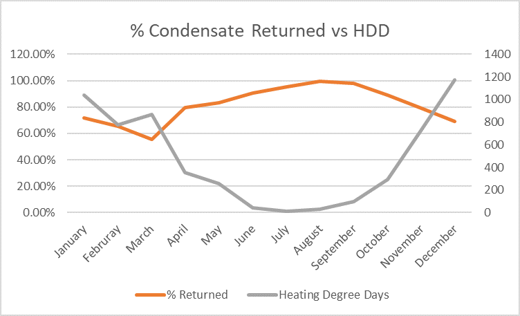
The method of calculating condensate losses through metered steam and water data has a margin of error greater than calculating losses with chemical testing methods. An example in the provided data set is where the heating degree days approach zero during the months of August and September the condensate return is 98% or better. This was unreasonable as losses attributed to the sterilizers and flash steam should be about 10 – 15% of the overall steam production. Regardless of the margin of error, the data indicated the condensate losses trending primarily to the heating months.
The analysis was developed and divided in to four (4) segments.
1. Steam Traps
2. Drip legs before AHU Control Valves
3. Condensate Return & Flash Tank Collection System
4. Condensate lifts in Lower Level Mechanical Rooms
For the analysis, SMI outlined existing conditions of each segment.
#1 – Steam Traps:
All accessible steam traps on air handlers, heat exchangers, humidifiers, horizontal unit heaters, and drip traps were tested with an ultrasound to determine functionality. Existing steam trap capacities were benchmarked against provided steam load (lb/hr) requirements for each AHU coil. Steam trap piping configurations for condensate return were analyzed for each location.
A failure rate of 53% for the steam traps associated with the air handlers was determined. The annual fuel losses due to failed steam traps were calculated at 6,494 (Mlb/yr) and recovered $64,494 in savings based on the steam cost of $10/Mlb.
For each AHU coil, the existing steam trap capacities were reviewed and compared against the steam demand. Three (3) locations had steam trap capacities rated below the demand of the AHU coil. Recommended measures were as follows:
The condensate piping on AHU’s in upper mechanical rooms appeared adequate with 6” – 16” of elevation drop from the bottom of each coil to the top of each trap. Condensate piping downstream of each trap flows through the floor dropping another 5’ – 10’ before dumping into the vertical condensate return stack. Each stack leads to the condensate collection system in the lower level mechanical rooms.
Lower level mechanical room AHU’s are designed with a 12’ – 14’ lift on condensate piping downstream from each steam trap. Some of the lower level AHU’s had the condensate return piping modified with return pumps installed to pump the condensate up the lift.
#2 - Drip legs before AHU Control Valves:

Improperly piped drip traps on the steam supply to air handlers were determined to be the cause of steam trap failures. In several locations, drip traps were piped from the strainer blow down just before each AHU control valve. Strainer blowdowns are designed to trap and remove debris from the system. The current configuration did not allow for debris removal resulting in debris accumulating in the traps or being reintroduced into the condensate return system.
As seen in the photo (figure 1.1), the strainer blow-down is being used as a drip leg for the steam trap, making the drip trap’s function impractical and the strainer blowdown port ineffective. This piping configuration exists on approximately 50% of the existing AHU steam supplies. The photo also shows the drip trap piped into the condensate return piping of the air handlers coil causing a potential for backpressure, water logging, and freezing.
#3 - Condensate Return & Flash Tank Collection System:
All HVAC and process equipment supplied by each riser (10 total) is returned and collected in a flash tank, then condensate flows to a condensate return tank before being pumped back to the energy center. Existing data on the flash tanks and return tanks was collected for all 10 risers. The dimensions, features, and adjoining systems were considered such as the load from HVAC equipment (heat exchangers, AHU’s, etc.)
The condensate and flash tank collection systems are not separated by mechanical means (figure 2.1). Instead, they share the same vent and are connected by open piping for condensate flow. This allows live steam to travel into the condensate return pump causing premature pump failures (figure 2.2).
These systems should work together but be piped independently from one another. The flash tank is in place to allow space for condensate to flash into steam or vent steam to the outside as needed. The condensate return tank & pumps are in place to collect and pump condensate back to the Energy Center. Separating the flash tank from the condensate return tank & pump through a mechanical device (steam trap) will protect the condensate return pumps in the event of trap failures elsewhere in the system. This will extend the life of the condensate pumps.

Figure 2.1 - Existing CR/FT Collection System Configuration

Fig 2.2 – IR of overheated condensate return tank
#4 - Condensate lifts in Lower Level Mechanical Rooms:
HVAC equipment in the lower level mechanical spaces discharges condensate into overhead condensate return mains located 12’ – 14’ above the elevation of AHU steam traps (Figure 4.1). The backpressure (head) created as a result of the lift decreased the pressure differential across the steam trap reducing capacity and efficiency of the heating coil. The site had been installing local condensate return pumps to eliminate backpressure (Figure 4.2). Pumping instead of “pushing” the condensate overhead will increase efficiency of the equipment, prevent coil damage from freezing, and improve overall condensate return.
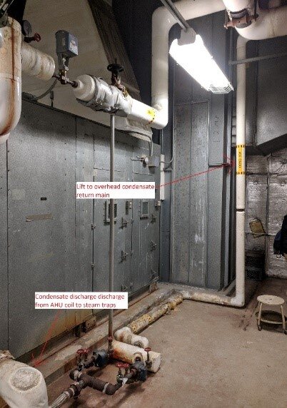
Figure 4.1

Figure 4.2
The outcome of the analysis was the development of permit-ready construction grade documents for public bid.
The energy savings and maintenance/operational savings associated with the recommended improvements is $110,000 annually and will be cash positive in 60 months. The improvements will dramatically improve heating capacity, reduce maintenance burdens, and improve occupant comfort and safety.
While the Detroit VAMC facility had unique conditions, our team’s expertise and decades of experience are universal and adaptable to other facilities. We offer each of our customers firsthand knowledge of diagnostic best practices for system functionality and design insight into their systems.
SMI offers construction-ready designs and solutions based on detailed assessments and energy savings calculations to dramatically improve system efficiencies.
Click here to contact us to schedule an audit or discuss your facility needs.