White Paper
Steam Boiler Feedwater Economizer
1. EXECUTIVE SUMMARY
A boiler feedwater economizer reduces steam boiler fuel requirements by transferring heat from the flue gas to incoming feed water. Boiler flue gases are often rejected to the stack at temperatures more than 100°F to 150°F higher than the saturated temperature of the generated steam. The boiler efficiency can be increased by 1% for every 40°F reduction in flue gas temperature. By recovering waste heat, an economizer can often reduce fuel requirements by 3% to 5% and pay for itself in less than 4 years.
This paper reviews the data necessary to assess and calculate the potential retrofit opportunities for installing feedwater economizers on boilers. A step-by-step methodology is laid out using existing baseline boiler operating data to establish the before and after operating conditions. The existing operating conditions are assessed to determine if they are in accordance with the Manufacturer’s recommendation.
The ability to recover waste heat is a function of the flue gas dew point temperature and the fuel-air ratio. Since lowering the flue gas temperature to below its dew point, it can cause acid corrosion in the economizer and the boiler breeching. For example, while 135 °F is standard dew point for natural gas fuel, this can fluctuate based on excess air levels and fuel-air ratios.
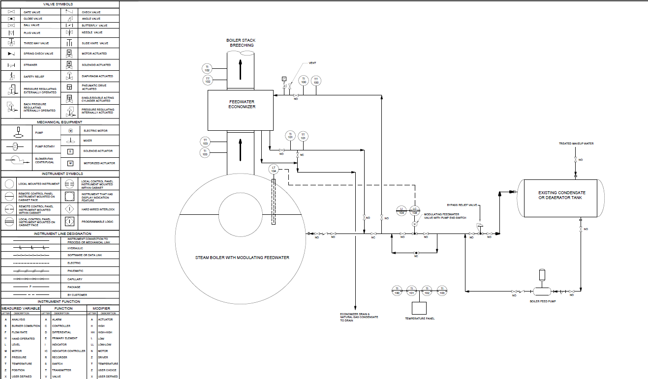
2. BOILER FEEDWATER ECONOMIZER DESCRIPTION
A boiler feedwater economizer is a heat exchanger that is installed on the stack of a boiler. It is designed to recover heat that would otherwise be wasted. The economizer transfers heat from the flue gases to the boiler feedwater, which helps to preheat the water before it enters the boiler. This reduces the amount of fuel that is needed to heat the water, which can save energy and money. A feedwater economizer is appropriate when there is available residual heat in the flue gas for increasing the feedwater temperature to the boiler. Boilers that exceed 100 boiler horsepower, operating at pressures exceeding 75 PSIG or above, and that are significantly loaded all year long are excellent candidates for an economizer.
3.0 BOILER ASSESSMENT AND BASELINE DOCUMENTATION
The existing boiler system should be evaluated to determine a baseline for efficiency and operating parameters. This requires a review and assessment of the boiler operating logs and site conditions. The following steps provide a guide for developing energy conservation and cost saving opportunity for installing a boiler feedwater economizer.
Document the boiler operating conditions. This can usually be done by reviewing the Boiler Log Sheets, performing a site survey, and summarizing the data applicable to the steam feedwater economizer retrofit. Such as:
Boiler Nameplate Data: including model and serial number.
Boiler Capacity: Rated capacity in Boiler Horsepower (BHP), pounds per hour (lb/hr), or million Btu input per hour.
Operating Pressure: Working steam pressure (psig), as this affects the saturation temperature of the water.
Fuel Type and Price: The primary fuel type (e.g., natural gas, 2 fuel oil, and cost to calculate economic returns.
Annual Hours of Operation: Total operational hours per year, including part-load conditions.
Load Profile: Whether the boiler operates at steady high loads or experiences significant variations, as this affects heat recovery stability.
Stack Gas Temperature: Temperature of the flue gas leaving the boiler at high fire (typically 400°F–500°F or higher).
Fuel Gas Recirculation (FGR) Rate: If used for NOx control, FGR increases the mass flow of flue gas through the economizer, requiring specialized design.
Excess Air Percentage: High excess air affects the mass flow and thermal energy available in the flue gas.
Part-Load Gas Temperatures: Expected stack temperatures at 75%, 50%, and 25% load
Feedwater Temperature (Inlet to Economizer): The temperature of the water entering the economizer (e.g., from a deaerator or condensate tank). Typical deaerator outlet is
~227°F, while condensate tanks are around 180°F.
Water Flow Rate: The mass flow rate of feedwater (lb/hr), including allowances for blowdown.
Condensate Return Rate: The percentage of condensate returning to the system vs. raw makeup water.
Stack Diameter and Layout: Physical dimensions of the stack for installing the unit, ensuring sufficient support for the equipment.
Draft Capability: Whether the existing fan can handle the added backpressure caused by the economizer.
Maximum Gas/Water Pressure Drop: Constraints on pressure drop for both the gas and water sides.
4.0 COMBUSTION EFFICIENCY ANALYSIS
Develop baseline boiler efficiency for the existing boiler system operation and fuel-to-steam efficiency. The standard for determining boiler efficiency in North America is the ASME Power Test Code (ASME PTC-4). For determining the efficiency savings associated with a steam boiler feedwater economizer, the applicable parts of the ASME PTC-4 are: 1) dry flue gas loss and 2) loss due to moisture from the combustion of hydrogen and 3) boiler surface radiation and convection losses.
ASME PTC-4 Indirect Method: Stack Loss Method
This method estimates stack losses of boiler efficiency. The parameters needed to calculate this method are given below. These data are measured during stack gas testing. Boiler combustion efficiency tests should be done at low-medium-high fire rates to determine the boiler efficiency operating range.
The dry flue gas loss accounts for the heat loss up the stack in the "dry" products of combustion, that is, CO2, O2, N2, CO and SO2. These carry away only sensible heat, whereas the “wet” products, mainly moisture from the combustion of hydrogen, carry away both latent and sensible heat. Environmental regulations limit CO emissions to about 400 ppm, and modern combustion systems usually produce much less than that, so from the viewpoint of efficiency CO can be treated as negligible. This simplifies the calculations.
Knowing the correct air to fuel ratio that achieves complete combustion, and the expected ratio of the products of combustion allows us to calculate how efficiently combustion has occurred. Having determined the boiler flue gas analysis, flue gas temperature and combustion air temperature, we can then make use of his data to optimize plant performance. Boiler efficiency at each test point can be obtained by adding up the losses, as determined by ASME PTC-4 procedures, and subtracting from 100. That is:
Boiler Efficiency = 100 – (LDG + LH + LR) Where:
LDG = Dry Flue Gas Loss
LH = Loss Due to Moisture from Combustion of Hydrogen
LR = Loss Due to Radiation and Convection
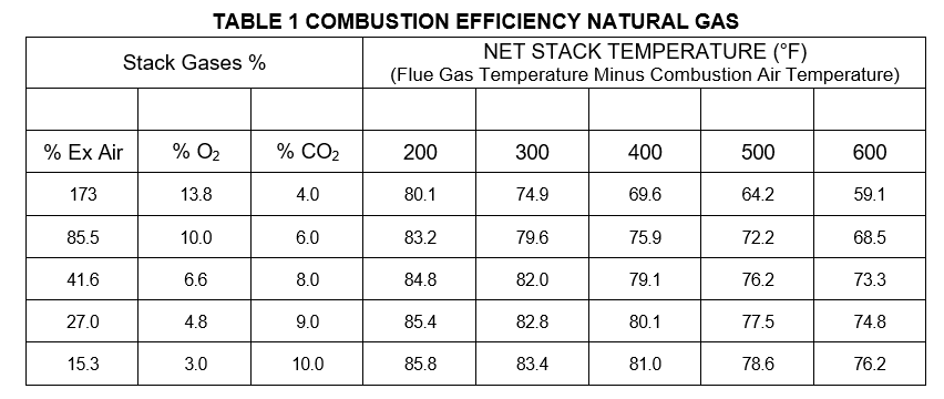
Using the data developed during the ASME PTC-4 calculations, a combustion efficiency table is prepared that contains the information required to evaluate and compare combustion efficiency for economizer retrofits. Information provided in a combustion efficiency table typically includes:
The % excess air
The % of oxygen in the gases of combustion
The temperature of the air supplied for combustion
The temperature of the gases of combustion when measured from the stack
Note: gases of combustion are also referred to as “exhaust gases” or “flue gases”. The term stack is used interchangeably with the words “chimney” and “breeching”.
A typical combustion efficiency table for natural gas is shown below.
5.0 EXAMPLE PROJECT
Existing Boiler without an economizer has the following data:
800 BHP Steam Boiler
Stack Temperature 470°F
Boiler Room Temperature 70°F
Water Inlet Temperature 210°F
BTUH Burner Input 33,580,000
Fuel Type Natural Gas
O2 Content 6.6%
Fuel Cost $8.00 per 106 BTUs
Annual Operating Hours 6,000
Annual Operating Fuel Cost $1,209,000
The 800 BHP steam boiler has a stack temperature of 470°F and burns natural gas. The boiler room temperature is 70°F. The air for combustion in the boiler is taken directly from the space surrounding the boiler, so we know the temperature of air supplied for combustion is the same as the boiler room temperature (70°F). The percentage of Oxygen (O2) in the stack gases of combustion is measured at the stack and has a value of 6.6%.
The temperature of the net stack is 470°F-70°F = 400°F
% O2 is 6.6%
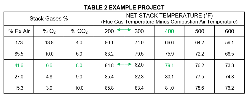
Checking the results with the combustion efficiency Table 2 (below highlighted in green) indicates that the boiler is operating at 79.1% efficiency.
The proposed retrofit would be to install a feedwater economizer and reduce the final exhaust stack temperature to 335°F. The new net stack temperature would then be 335°F-70°F = 265°F. Checking the results with the combustion efficiency Table 2 this project indicates that the new boiler efficiency would be between 200°F and 300°F net stack temperature. The interpolation calculation below shows the new efficiency to be 83 percent.
New Efficiency = 84.8 + (265-200) X [(82-84.8) / (300-200)] = 83 percent And the energy and cost savings would be:
Percent Savings = 1-(79.1% / 83%) = 4.7%
Cost Savings = 0.047 X $1,209,000 = $56,823
The design-build installed cost is $156,000 and results in a simple payback of 2.7 years
Steam Management performs design-build engineering and construction management services for economizer projects. Design engineering includes field testing and site survey of the existing installation with a final detailed report and calculations listing the proposed cost savings and required site modifications. Once the Owner determines to move forward with the project. Steam Management will perform final design engineering and provide stamped mechanical, electrical and P&ID drawings. During construction, we provide project management and commissioning services for the Owner’s preferred licensed pipefitters and electricians for the installation of new equipment, mechanical, electrical, structural to install the measure per final design drawings and specifications.